Issue 389, April 1985

|

|

Download
Issue Details
- PS Editor
- Don Hubbard
- Graphics Company
- Perspective Instructional Communications, San Diego, California
- Artists
- Steve High
- Jeff Jonas
- Location
- Lexington-Blue Grass Army Depot, Lexington Kentucky
Source Credit
- Original source materials provided by LOGSA Redstone Arsenal, Alabama and Scanned by Radionerds.
Feedback
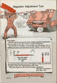
In January 2016 SFC Mark GreenBaum wrote to tell me about his experience with sending in a tip to PS Magazine, below is his story...
Chris,
Thanks for your reply.
I entered the Army with four years Air Force time in service so I began my career in the Army at Fort Knox Armor School as 63D10, Self-Propelled Field Artillery Systems Mechanic, which included the M113 family of vehicles (FOV). When I got to Germany, the motorpool issued me a basic mechanic’s tool kit but it didn’t include a small screwdriver. I was having a hard enough time trying to get a replacement empty toolbox to replace the damaged one I was issued, let alone a small screwdriver. Supply thing I suppose. And I didn’t want to buy one either.
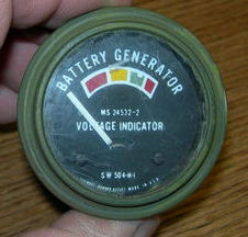
The problem was the standard voltage indicator on the M113A2s and M577A2’s wasn’t very accurate. There was a very-low battery charge (red) area, a low battery charge area (yellow) a green area with a “dot” that was supposed to be at 26.5 VDC for the 24 VDC charging systems to indicate the batteries were being charged and then the overcharge area (red). The tracked vehicle drivers assumed the “dot” was the correct position for the needle when the engine was running and would disassemble their army-issue black ball-point pens, remove the copper ink tube, flatten it, and adjust the voltage regulator which was located right next their left knee until the needle reached the “dot” in the green area.
Problem is that the gauge wasn’t correct. Sometime adjusting the regulator up to the needle would put over 30 VDC into the batteries and it wasn’t long until they were stinking of sulpher and boiling. Remember these were 50 to 100 amp charging systems. Our shop chief began to make a point for the mechanics to go out to the vehicles with a multi-meter (STE-ICE was new and as far as we were concerned it was a bulky, over-priced, multi-meter and tire gauge) and adjust the regulator to 26.5 VDC regardless of where the needle pointed on the indicator.
The idea began in Grafenwöhr, with a small piece of straight welding rod, hammered, filed into a screwdriver head, and then wrapped with duct tape. It would work but I wanted more leverage. That’s when I decided to make them from wire hangers and added the ninety degree one inch handle, to give the mechanic a little more leverage and to be more accurate when making the voltage adjustments. I could make half a dozen of them in an hour with a vise, a pair of pliers, a hammer, and a file. I eventually made one for every mechanic, including the wheeled vehicle mechanics because it fit the regulator on the 5-ton trucks as well.
On a whim I sent my idea in to PS Magazine early in 1985. Not long after, during a BN Commander’s call, I was given a very nice certificate from PS Magazine. It must have been 18” x 24” framed and it had apparently come down first through 3rd ID HQ in Würzburg, to the battalion accompanied by letters of congratulations from each commander above battalion it passed by on the way down to me. To this day I have a poorly laminated copy of the page backed with cardboard as well as a complete copy of the magazine.
Thanks again for the fix.
Mark Greenbaum
Sergeant First Class, US Army (retired)

